
TL;DR: The stainless eyebolt has such a small effect on the tuning of the transformer it can be safely ignored as a factor. For the full investigation into this question and why you should care, read on.
One of the things I’ve learned about EFHWs is they are rather sensitive to their surroundings, or at least the transformers are. The transformer is a tuned circuit performing a large impedance transformation. As a tuned circuit, it has resistive, capacitive, and inductive components. Ideally, the capacitive and inductive components cancel leaving a purely resistive load at the frequency of operation. Since this is a broadband transformer, we can’t adjust the capacitive and inductive reactances when in operation. Instead, we have to make a best effort to tune the transformer for optimal performance in our desired environment and then operate the transformer in such a way as to maintain that performance. Stray capacitance or inductance in our design may result in a less than optimal result.
So what does that mean? It means ensuring we do not introduce anything in the environment around the transformer that might affect the tuning.
My linked EFHW transformer design uses a stainless steel eyebolt to carry the tension between the support and the suspended wire elements. Mechanically, this is a great arrangement as it takes any lateral stresses off the polycarbonate enclosure and places them on a steel component that won’t bend, warp, or crack in extreme heat or cold.
The stainless eyebolt is very near the output of the transformer, however, so we can’t discount the possibility of it affecting the tuning and performance of the transformer. I’ve had it in mind to do some testing with and without the eyebolt to measure the effect it has and finally got around to doing so this past weekend.


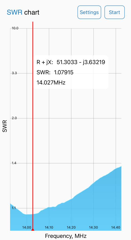
Removing the eyebolt shifted the SWR null on the 20m band down 26khz. At this frequency, the result is inconsequential. Using the classic formula for the length of a halfwave antenna in feet as 468/f, we find the difference here is the equivalent of a mere 0.7″ of wire.
On 30m, the SWR null shifts only 12khz. As you move down in frequency the effect will eventually disappear. For the purposes of this project, a linked EFHW covering 80-20m, it can be safely ignored. On higher frequencies, however, it might be a factor.
Given the direction of the observed shift, it is safe to assume the eyebolt is acting as a small stray inductance in the system. In practice, stray capacitance is much more likely to be a problem while fielding the antenna. While I had the antenna up and hooked up to the analyzer, I measured this effect by placing my hand near the transformer while running a sweep.
Holding my hand near the transformer output shifted the SWR null a whopping 248khz. In our operating environment, there are many things that can cause the same effect. Wet trees or leaves, the earth, or a nearby metal building or roof can all have drastic affects on the performance of an EFHW. This is why I recommend keeping your EFHW transformer at least six feet away from nearby objects, especially when first tuning the antenna so you have a reliable baseline.
I am working on learning OnShape so I can design a 3D printed enclosure for my linked EFHW. The results of this testing are encouraging and will give me more flexibility in my design.
Padre

One thought on “Linked EFHW: What if We Remove the Conductive Eyebolt?”