Antenna Library: QMAC QM7005 Terminated End-Fed

QM7005 antenna kit. Includes coax, halyard line with integrated throw weight, ground spike, antenna, and winder.

QMAC electronics was an Australian firm who produced affordable portable and mobile HF radio equipment. Their target market was aid agencies, NGOs, scientific expeditions, and military/paramilitary organizations. Their core product was the QMAC HF-90. Remarkably small for it’s time, the HF-90 boasted up to 50W of transmit power, frequency hopping, and easy field serviceability.

One of products in the QMAC catalog was an interesting terminated end-fed antenna, model QM7005. The antenna is considered terminated because of a load resistor installed in series along the transmitting element. It is an end-fed because it uses an unbalanced-to-unbalanced transformer (UNUN) to feed a long wire against a short ground or counterpoise wire. This antenna was marketed for HF manpack use or as emergency antenna for mobile operations.

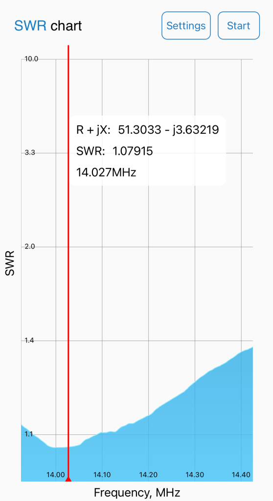
The terminating load on this antenna is intended to deliver broadband coverage with acceptably low SWR from 2-30 Mhz. The HF-90 could handle SWR up to 3:1 and later models had significant built in protection for the RF final amplifier.

The included instructions recommend two deployment variations. The preferred method is to use a vehicle as tie off and grounding point. Alternatively, one may deploy the antenna counterpoise along the ground.

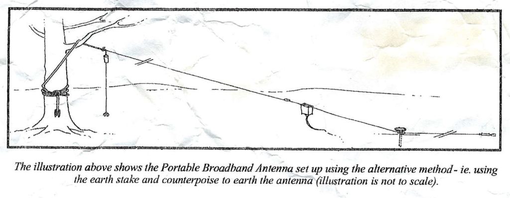
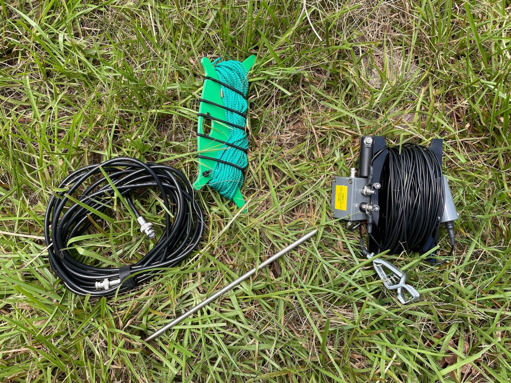
Ordinarily, I don’t drive a vehicle out to the areas I operate in so I decided to test the antenna using the alternate method pictured above. All the guy points needed to achieve this deployment come integrated into the antenna. Below is the NanoVNA sweep of the antenna from 1.5-30 Mhz.

VSWR sweep of the QM7005 using the alternate deployment method.

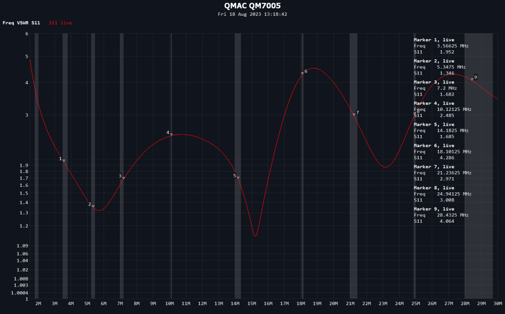
The QM7005 kept VSWR below 3:1 from about 2 Mhz up to about 17 Mhz. Above that point results varied significantly by frequency. For most purposes where this antenna and radioset would have been deployed, namely local and regional communication, this performance would have been sufficient. The most consistent performance for an antenna like this occurs on the NVIS frequencies anyhow as the radiating pattern of the higher bands ceases to be omni-direction and instead breaks ups into an increasing number of lobes and nulls.

In case someone would like to build or experiment with this type of antenna, I went ahead and reverse engineered it.

Moving from left to right on the diagram starting with the ground connector, a simple spring loaded alligator ground clip is used. The UNUN in my sample was wrapped with tape and sealant so I couldn’t discern the winding pattern without risking destroying it. Using a 450ohm resistive load, however, I was able to confirm it was a 9:1 ratio. The design used by QMAC was not as broadband as it could be if it used a different core or winding pattern. If you decide to build your own, I recommend using a FT140-43 toroid from Fair-rite as these give good broadband performance well above 30 Mhz. Lastly, the terminating load is a 1.1k ohm resistor. Again, I wasn’t able to disassemble the load for inspection but any non-inductive power resistor from Ohmite should work for this application.

While in the field, I used this antenna to check Winlink email and had no difficulty connecting to my usual gateways within NVIS range.

For your reference, I’ve also scanned a copy of the QM7005 Instruction Manual.

Padre

SurvivalComms EFHW Shootout

Bret from YouTube channel SurvivalComms published a comparison of several EFHW transformers. He too found the Fair-Rite 2643251002 to be a superior performer.

My only critique is that back-to-back testing of transformers isn’t good for absolute testing of transformer loss. Testing this way includes mismatch loss that would otherwise be cancelled out by a tuned wire. The mismatch loss I’m referring to is like running a high SWR coax on your coax and exaggerates how lossy these are.

Core loss in with a FT240-43 toroid with 2 turn primary.
Core loss in a 2643251002 toroid with 2 turn primary.

Bret’s testing is a good relative comparison though and his thermal testing clearly shows how lossy the common design on an FT-240-43 toroid is. I need to get around to some thermal testing on my 81:1 UNUN.

Having passed around my EFHW design for some third party testing I will say a high efficiency design isn’t for everyone. More thoughts on that in a future post.

73,

Padre

Linked EFHW: What if We Remove the Conductive Eyebolt?

81:1 UNUN with conductive metal eyebolt removed for testing.

TL;DR: The stainless eyebolt has such a small effect on the tuning of the transformer it can be safely ignored as a factor. For the full investigation into this question and why you should care, read on.

One of the things I’ve learned about EFHWs is they are rather sensitive to their surroundings, or at least the transformers are. The transformer is a tuned circuit performing a large impedance transformation. As a tuned circuit, it has resistive, capacitive, and inductive components. Ideally, the capacitive and inductive components cancel leaving a purely resistive load at the frequency of operation. Since this is a broadband transformer, we can’t adjust the capacitive and inductive reactances when in operation. Instead, we have to make a best effort to tune the transformer for optimal performance in our desired environment and then operate the transformer in such a way as to maintain that performance. Stray capacitance or inductance in our design may result in a less than optimal result.

So what does that mean? It means ensuring we do not introduce anything in the environment around the transformer that might affect the tuning.

My linked EFHW transformer design uses a stainless steel eyebolt to carry the tension between the support and the suspended wire elements. Mechanically, this is a great arrangement as it takes any lateral stresses off the polycarbonate enclosure and places them on a steel component that won’t bend, warp, or crack in extreme heat or cold.

The stainless eyebolt is very near the output of the transformer, however, so we can’t discount the possibility of it affecting the tuning and performance of the transformer. I’ve had it in mind to do some testing with and without the eyebolt to measure the effect it has and finally got around to doing so this past weekend.

20m as-built results with eyebolt in place.
20m results with eyebolt removed.

Removing the eyebolt shifted the SWR null on the 20m band down 26khz. At this frequency, the result is inconsequential. Using the classic formula for the length of a halfwave antenna in feet as 468/f, we find the difference here is the equivalent of a mere 0.7″ of wire.

On 30m, the SWR null shifts only 12khz. As you move down in frequency the effect will eventually disappear. For the purposes of this project, a linked EFHW covering 80-20m, it can be safely ignored. On higher frequencies, however, it might be a factor.

Given the direction of the observed shift, it is safe to assume the eyebolt is acting as a small stray inductance in the system. In practice, stray capacitance is much more likely to be a problem while fielding the antenna. While I had the antenna up and hooked up to the analyzer, I measured this effect by placing my hand near the transformer while running a sweep.

Holding my hand near the transformer output shifted the SWR null almost 250khz!

Holding my hand near the transformer output shifted the SWR null a whopping 248khz. In our operating environment, there are many things that can cause the same effect. Wet trees or leaves, the earth, or a nearby metal building or roof can all have drastic affects on the performance of an EFHW. This is why I recommend keeping your EFHW transformer at least six feet away from nearby objects, especially when first tuning the antenna so you have a reliable baseline.

I am working on learning OnShape so I can design a 3D printed enclosure for my linked EFHW. The results of this testing are encouraging and will give me more flexibility in my design.

Padre

A Portable Linked End-Fed Half-Wave (EFHW)

UPDATE 15 August 2023: I’ve accomplished some testing to determine if the eyebolt used in this design introduces stray inductance or capacitance. Read about that testing here.

Starting in the fall of last year, I began working on a linked EFHW for portable HF radio. Almost all of my amateur radio activity revolves around portable ops. Parks on the Air (POTA) is a major interest as well as keeping my skills sharp for the unexpected.

As many portable operators have found, the EFHW is often the ideal balance of portable convenience and efficiency. I wasn’t satisfied with commercially available products, however, as I wanted an antenna with more control over the radiation pattern and a rugged build to match the needs of an adventurous field operator. Thus this project was born.

Rather than just copy existing designs, I made an effort in the project to further my understanding of the properties of EFHW antennas and use the latest build techniques and materials for improved efficiency. This effort builds on suggestions published by Evil Lair Electronics on YouTube, Owen Duffy, VK1OD, and Colin Summers, MM0OPX.

I’ve attempted to document all my findings in a comprehensive paper. The current draft is located in the Files section on this site. I still have a number of goals for this project so stay tuned for updates in the coming weeks and months.

I would very much welcome feedback on this project if you have suggestions for improvement or if you found this useful.

Padre