I don’t often use HTs but when I do I want two things. First, I want a speaker I can hear. Many rugged HTs are guilty of being difficult or impossible to hear outside of a quiet room (I’m looking at you VX-8DR). The second thing I want is good battery life. I should be able to charge it and put in on the shelf for a while and still have useful life in when I need it (I’m looking at you TH-D74). So when Icom announced the IC-T10 I went ahead and pre-ordered one through HRO.
On the two points above, I have not been disappointed. It has great battery life and rarely needs to be charged. The speaker is plenty loud so can be heard in a moving vehicle or noisy venue. It isn’t the best sounding receiver but it is plenty intelligible. It is a direct conversion receiver with all the baggage that comes with that. Namely, it is easy to desense in a strong RF environment and it is prone to intermod. If you understand those limitations it is a fine, rugged radio that is very usable for analog FM operations.
At the onset, this radio lacked a published MARS/CAP mod. Recent increased attention on bad actors may have the manufacturers thinking twice about offering this option. Worry no more though, the IC-T10 does have an option to expand the TX range to match the RX range of the radio. Since the radio appears to be heavily based on Icom’s Part 90 offerings it makes sense the hardware was capable all along. HRO now offers this mod at time of sale but it’s a whopping $80! We’ll see why as we move along.
I found the mod published at mods.dk. As a hat tip them, I won’t republish their work here but rather encourage you to support their work by signing up for an account. What I will do is validate that their published mod works and provide a few details from my experience.
The mod involves moving a 47K resistor from one pad to another. Easy right? Well, the resistor is a 0402 package SMD resistor. Its about the size of two grains of sand. Gratefully, I’m blessed with excellent near vision and can normally pull off this sort of thing with the naked eye. I was able to remove the resistor but in the process lost it on the workbench somewhere. So I had to order another from Mouser. Since they were pennies a piece I ordered 10.
Since I had to wait anyway I broke down and ordered an inexpensive magnified headset with light on Amazon. Here is the model I ordered. I’m sure most of these are the same but I can say this was entirely sufficient for what I wanted to do and should prove handy in the future.
The 47K resistor that needs to move for this mod is circled in red. This photo was taken with 2x telephoto on my iPhone through the 3.5x lens on my magnified headset. Yes, it is that small.
The photo above shows the resistor in question. The bare pad is where the resistor was initially. You are supposed to move it down to the bottom pad on that trace. You’ll notice that I ended up with a cock-eyed resistor. This was my second attempt on this resistor so I was starting to get nervous about damaging the PCB. I ops checked this and it worked so I left well enough alone at this point and put it back together. Normally, I take a lot of pride in my solder work but I’ll admit I haven’t done very much SMD rework. I’ll certainly look for opportunities to get more practice moving forward.
Here is what I learned working this project. 1) Magnification is good. Even with good eyesight this was too small for me. 2) Clean your contacts well after removing the part so that you can get it to sit flush in its new location. 3) Use an appropriately small tip. Videos showing the technique of wide solder tips across two terminal devices didn’t work for me. 4) Chip Quik no-clean solder flux works great. 5) It wouldn’t hurt to invest in a hot-air rework gun for these jobs. 6) Even after buying a few extras, I came out ahead vice having someone else do this and had the benefit of learning some new skills.
Know your limits but realize if you never push them you’ll never make any progress. It might be ugly but so long as it works, who cares!
There is nothing better than combining portable HF radio ops with an overnight trip to the backcountry.
According to the league, the stated objective of Field Day is:
To contact as many stations as possible on the 160-, 80-, 40-, 20-,15- and 10-Meter HF bands, as well as all bands 50 MHz and above, and to learn to operate in abnormal situations in less than optimal conditions.
ARRL Field Day is one of my favorite activities on annual calendar of ham radio events. So it is for many other amateur operators. So popular, in fact, the included bands are wall to wall signals. This can be a frustrating experience for those who are serious about operating low power “in abnormal situations in less than optimal conditions.” Optimizing for ARRL Field Day doesn’t necessarily mean you have a practical station for the types of contingencies the league hopes you are preparing for.
Winter Field Day seems to attract more practical minded participants. Cold weather seems to weed out the faint of heart. Still, it operates on the same rules as summer Field Day so still encourages a contest mentality.
As an alternative for 2023, Gaston, KT7RUN, came up with the idea of Anti-Field Day (AFD). The concept was to operate during the same operational period as ARRL Field Day but do so on the WARC bands where, by gentleman’s agreement, contest activity does not occur. Instead of the make as many contacts as possible contest mentality of Field Day, the objective of AFD was to make targeted contacts with a pre-determined list of participants. This required actual communications planning to determine the bands and times most likely to permit contact with the target stations. JS8CALL was chosen as the operating mode for its excellent weak signal characteristics, automation capabilities, and ability to store and relay messages for stations that are outside of your coverage area.
Planning
I was on vacation to Michigan during AFD so planned to operate from there. The challenge of operating from an off-grid field location was irresistible so I started looking for options near where I was staying. A friend turned me on to the Tin Cup Springs Off-Road Vehicle (ORV) trail in the Pere Marquette State Forest. After doing a map recon and confirming that dispersed camping was allowed there I committed to this location for AFD.
I’ve had a subscription to Gaia GPS for a couple of years now and it proved an excellent tool for conducting a map recon of the operating location. In addition to accessing countless maps from topos to satellite imagery over the internet, Gaia GPS allows you to select map layers to and locations to save off-line so these maps were available to me even off-grid.
In the image above, I’ve circled the area I identified in advance as my preferred site to setup camp. This area was off the main trail and slightly elevated. Since distance contacts where going to be required I didn’t want to setup in a valley that might block lower RF take-off angles. Once I arrived here, I parked and surveyed the area. This entire area is heavily wooded so there was enough clear ground to setup camp but not much more.
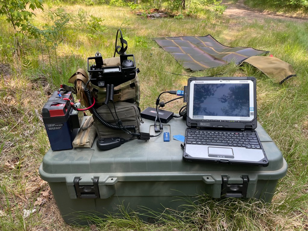
Luckily, I knew AFD was in the planning before I departed and so was able to pack the gear I thought I would need. For this outing I took my FT-857D and End-Fed Halfwave (EFHW) antenna kit. For power, I took a supplemental 23AH LiFePO4 battery to augment the 10AH battery packed with the radio. Additionally, I brought a 100W Powerfilm solar panel. Past experience with this combo gave me confidence that I would be able to operate off-grid all weekend if needed. Lastly, I had 2x CF-20 Toughbooks with me as I was in the process of setting up a new one when I left home and wanted to keep working on it on the road. This would prove fortuitous as we shall see later.
It is worth pointing out that this is a fairly heavy load to carry. I would hike with it for a day it would be too much for a multi-day man portable hike for a single person. On the other hand, one needs to be realistic about power needs when operating a 20W radio and laptop for 24 hours in the field. A less power hungry QRP rig would draw less power but would have reduced the chance of successful contacts coast to coast. Everything is a compromise but for this deployment I chose to pack for a vehicle borne mission and kitted out accordingly.
Early in the planning for AFD it looked like 12m, 17m, and 30m would all be included in the comm plan. Since my EFHW kit only covers 30m I built a linked dipole using a combination of hardware store materials and gear I had with me.
Execution
On arrival to the site, my most important task to was to deploy my antenna. I was flexible on where the rest of my equipment would go but I knew most of my contacts were going to be south and west of me so wanted to deploy my EFHW accordingly. A sloper configuration is mildly directional so luckily I had a tall tree at the site with enough adjacent space to allow me to orient it to the southwest.
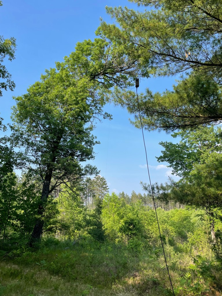
30m EFHW deployed for Anti-Field Day 2023. The apex of the sloper was about 45′ up in the curved tree in the background. It sloped down towards the southwest leaving the transformer about 8′ above ground.
I used the tonneau cover on my Ranger as space to unfold the solar panel. The radio and computer were hooked up next to the truck and I was on the air in time to send my first JS8call heartbeat 20 minutes before startex.
As it turned out, this was too close to the antenna and I started having RFI issues with the CF-20 about 30 minutes into the exercise. I’ve experienced this issue a couple of times before. With the CF-20, too much RF causes the touchpad and USB ports on the docking station to lock up. Recovering from this requires powering off the Toughbook and removing the batteries long enough to reset the hardware. This is the first time I’ve had this issue with my EFHW. While end-fed antennas have a reputation for causing RFI issues, I have measured this with an RF current meter and found my EFHW to be comparable to a dipole with no BALUN.
The RFI issue wasn’t an immediate show stopper. The CF-20 features a touch screen as well so I was able to continue operating for a time while I troubleshot the issue. Moving my operating position further from the antenna was all I needed to do. I had a second CF-20 with me so, being impatient to get back on the air, I used the backup for several hours and had no further RFI problems.
I moved a couple more times throughout the day chasing the sun. I wanted to optimize my use of solar to keep the battery charged for overnight ops so had to keep the panel exposed as the sun moved lower in the sky. Being in a small clearing meant having limited areas of sun exposure throughout the day. While it wasn’t a big deal, finding a larger clearing will be a consideration next time I do an event like this.
My car camping box made for a great expedient field desk during this exercise.
My laptop power supply also gave me RFI issues. Recently, I found a good deal on a case of Lind Toughbook power supplies. The advantage of these units is their dual voltage capability. Namely, they can run of 120VAC or 12VDC thus saving you from having to carry two power supplies. Lind builds these for the emergency services market and they have a good reputation. Unfortunately, I found that this power supply creates a measurable amount of noise on HF frequencies. Testing at home after the exercise confirmed these are generating a large amount of RFI due to a ground loop of some kind. The issue couldn’t be resolved with ferrite but did go away when the laptop and radio were powered by separate batteries. This isn’t practical for me so I may be ditching my Lind power supplies and reverting back to the PWR+ units I’ve used for the last two years in the field with no issues. The Lind units I have are model CF-LNDACD90. Lind makes many models and it could be that others do not suffer from this issue.
The remainder of exercise execution occurred in accordance with the comm plan without any issues. I operated from 1800 UTC Saturday to 1500 UTC Sunday. Others may have continued operating on Sunday beyond 1500 UTC but thunderstorms were coming in. That said, activity had largely tapered off by that point. During the operational period, I was able to make contact with almost everyone participating, either by direct contact or by relay.
Conclusion
Here is a summary of what I learned this weekend.
SUSTAIN: 1. The FT-857D and EFHW antenna kit both performed well and were easily adapted to the requirements of this exercise. 2. JS8CALL is an excellent weak signal mode with features that enable effective asynchronous communication. 3. The comm plan was well developed and allowed almost everyone to participate fully. 4. Continuous training with the same equipment builds familiarity and accelerates problem solving when issues do occur.
NEEDS IMPROVEMENT: 1. There was no pre-execution brief for participants. Having one would have clarified the requirements for all participants. 2. The COMMPLAN did not directly address relays or MSG deposits, at least in the example log provided. I suspect I contacted more folks than I logged because of this. 3. The first few comm windows had issues with simultaneous TX and the channel capacity with all the participants. A net control operator should be assigned or a staggered TX plan established to reduce the need for re-transmits. 4. Not all participants switched to slow mode on the schedule prescribed by the comm plan.
All in all, this was a great event and I look forward to participating again in the future. Next time I may try to challenge myself by operating entirely out of a rucksack instead of a vehicle. This would challenge me to use a lighter kit all around.
I’m travelling at the moment but need a WARC band antenna for TTP’s Anti-Field Day event coming up this weekend. I have individual antennas that cover 30m and could cover the other bands with a tuner but I decided to go to the hardware store and see what I could come up with. With some speaker wire, zip ties, and WAGO connectors I was able to put together a nice linked dipole to cover 12, 17, and 30m.
WAGO connectors and zip ties work remarkably well for a quick linked dipole.
This project was my first use of WAGO connectors. It was just happenstance that the local hardware store, Menard’s, had them. While familiar with them, I’ve never seem them in a store before. They probably aren’t the most durable solution but but they are small enough and convenient enough that I’m adding them to my radio possibles pouch for future improv solutions.
The cobra head and N9SAB nano BALUN are part of my normal portable radio kit so were already on hand to provide a feedpoint for this project. With the arborist throw weight and cordage from my EFHW kit I have a complete system ready for this weekend.
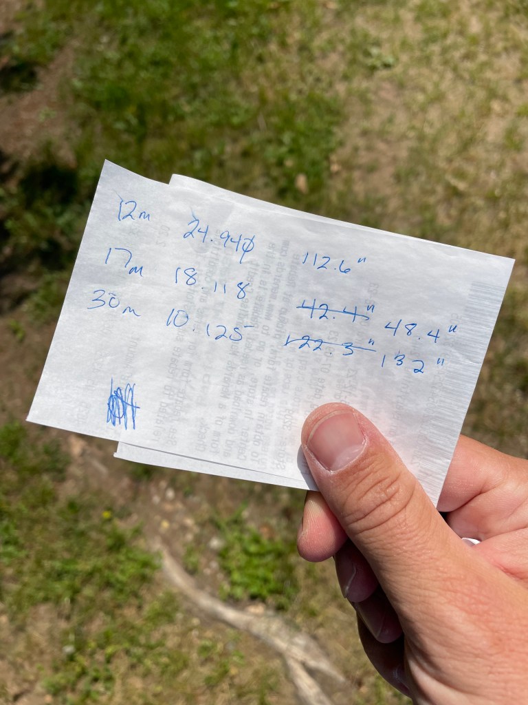
The whole project took about two hours to complete. It would have gone much quicker but I got cocky and decided to cut my elements right at 234/f after 12m ended up right on. It turns out 17 and 30m needed to be longer so those elements got cut twice….
My final dimensions for the WARC band linked dipole.
Hopefully this provides inspiration for your own projects.